Main Page
From MontiArcTraining
Getting Started
Get the tutorial materials
- Download the tutorial eclipse version that includes MontiArc
Setup the IDE
MontiArc is based on Java and employs Apache Maven for its dependency management and build process. Therefore, MontiArc models (and the language itself) can be developed with any IDE that supports Java and Maven. However, we recommend to use the Eclipse IDE and this tutorial project provides you with a prepared Windows version of Eclipse Portable containing all required plugins.
- Optional: If you want to use the provided Eclipse that is located in folder Arclipse.zip, you only have to start it and select 02.Workspace as your workspace. Because Eclipse uses the currently installed Java, you may check whether Eclipse is using a JDK. Therefore go to Window -> Preferences Java -> Installed JREs. If you are running on a JRE you have to add the path JDK installation and select it. Afterward, you can continue with Step 2 of this tutorial.
- Optional: If you do not use Windows, but want to use Eclipse, you can still use the Eclipse editor plugin (located in Aclipse/App/dropins/MontiArcEditor-1.0.0.jar ) by copying it into the dropins folder of your Eclipse installation.
- Optional: If you want to use a different IDE than Eclipse, make sure you set it up such that it uses a recent version of the Java JDK (SDK is not sufficient!), supports to build projects with Maven, and SVN or git for version control.
Import Task Projects
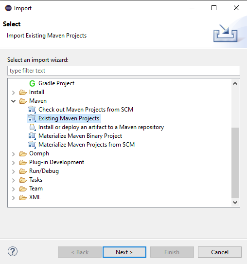
Import the task project into your workspace, by using the Maven import Existing Maven Project functionality. To open this menu, right-click into the Project Explorer and choose Import.... The dialog depicted
in Figure 1.1 should appear.
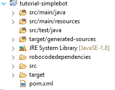
Now choose the folder /<<PROJECT>> and select the pom.xml of the task project. Afterward, the example project should appear in your project explorer. Make sure that Eclipse recognizes the correct source folder locations. This is important to resolve the package names for Java classes. The project layout should look similar to the structure shown in Figure 1.2.
Please note that the target folder will be empty until the code generator has been executed. To this effect, target/generated-sources cannot be selected as source folder until then.
| Figure 1.1: Eclipse dialog for importing new Maven projects | Figure 1.2: The folder structure of the task project after the import. |
Setup Robocode
This tutorial will use Robocode to evaluate the architectures that you build. To use Robocode download and install RoboCode
FAQ and Troubleshoot
- Which versions are used in this tutorial?
- -This tutorial uses MontiArc in version 5.1.2, Eclipse Oxygen June 2017 and Java 1.8 jdk.
- Running Maven or Java fails:
- -Make sure your IDE is using a Java 8 JDK. How to set the JDK in Eclipse is described in Section 1.1.
- I'm getting NullPointerExceptions in my handwritten Java code:
- -Make sure that you check all incoming Ports for emptiness. If there is no value on a port set, its value is
null. For instance, if you want to check whether the port value of a portmovementis empty, just callinput.getMovement() != null.
- -Make sure that you check all incoming Ports for emptiness. If there is no value on a port set, its value is
- My Java code is not compiling:
- -This can have two reasons. Either your implementation is incomplete or you have not added the folder
target/generated-sourcesas source folder to your project in eclipse. To set a source folder right-click on the folder, then selectBuild Pathand left-clickUse as Source Folder.
- -This can have two reasons. Either your implementation is incomplete or you have not added the folder
- Error in se-groovy-maven-plugin
No Value Present:
- -Check whether the package and name of the file are the same like the ones in the model.
- Error from Figure 1.3 occurs: Just ignore it and click
finish. - When importing my robot, it is not shown in the
Battledialog:- Restart Robocode and try again.
- Check the Robocode console for exceptions or other error messages.
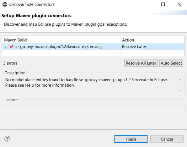
Finish.
Challenge 1: Developing DETLEF
In this challenge of the tutorial, you will implement an architecture for a robot called simple \detlef. In the course of this challenge, you will learn the basic concepts and modelling elements of MontiArc. For this, Section 2.1 presents the basic concepts of MontiArc necessary to understand the following tasks. Then Section 2.2 shortly describes Robocode, which we will deploy the architecture build in the tasks to. Thereafter, Task 1.1 wants you to implement your first MontiArc component, then, Task 1.2 teaches you how to create a decomposed component. Task 1.3 lets you connect subcomponents and in Task 1.4 and Task 1.5 you will implement a component's behaviour by using AJava and handwritten extension of generated classes.
For this chapter, please import the project challenge-01 as described in Section 1.2.
MontiArc Basics
MontiArc is a component & connector (C&C) architecture description language (ADL) and modelling infrastructure for the development of distributed systems [Wor16] [RRW15]. The language's infrastructure comprises code generators translating models into an arbitrary general-purpose language (GPL) realization. MontiArc is intentionally designed to be light-weight to keep the language easy to learn and flexibly adaptable. Thus it aims at providing only the most important modelling elements of C&C ADLs and focuses on language and toolchain extensibility. The provided elements are exactly the fundamental elements of architectural descriptions: components, connectors, and configurations. Components are the units of computation in an architectural model and yield well-defined interfaces via typed, directed ports. Connectors connect the interfaces of components to realize component communication. A configuration is a graph of components and connectors that describes component composition.
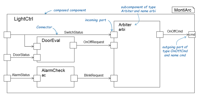
Following this principle, MontiArc facilitates modelling C&C software architectures with hierarchically structured, interconnected components. The interface of a component is defined by typed directed ports. Components receive messages via their incoming ports and emit messages via their outgoing ports. Unidirectional connectors connect exactly one source port to one or more target ports. To facilitate component reuse, MontiArc distinguishes between component-types and component instances. A component-type (denoted "component" in the following) defines the interface of its instances by a set of ports and may comprise component instances ("subcomponents") and connectors defining a configuration. A component instance is an instantiated version of a component-type used as a subcomponent. If a component contains subcomponents, it is called composed. Otherwise, it is called atomic. Atomic components perform the actual computations of a system. The behaviour of a composed component is completely derived from the composition of the behaviours of its subcomponents according to its configuration. The behaviour of atomic components has to be implemented by hand, i.e., by providing GPL code implementations. MontiArc provides further language features, such as generic type parameters, configuration parameters, and syntactic sugar for automatically connecting all ports of the same type. A complete description of the MontiArc ADL is available in [12]. Figure 2.2, for instance, depicts the graphical representation of the component type LightCtrl.Listing 2.1 shows its corresponding textual definition. The component consists of four ports (l. 2), three subcomponents (ll. 4--6), and seven connectors (ll. 8--13). The incoming port switchStatus of componentLightCtrl, for instance, is connected to the same-named and same-typed incoming ports of the subcomponents arbiter and doorEval (l. 9).
What is Robocode?
Robocode is a programming game where the goal is to program a robot to compete against other robots in a battle arena. The player is the programmer of the robot, who will have no direct influence on the game. Instead, the player must write the artificial intelligence of the robot telling it how to behave and react to events occurring in the battle arena.
The game will help you learn MontiArc, and have fun doing it. The robot's components and their behaviour are written in the MontiArc modelling language. The Robocode game can run on any operating system supported by the Java Platform, which includes all common operating systems like Windows, macOS, Linux, etc.
Robocode battles take place in a battlefield, where small automated 6-wheeled robots fight it out until only one is left. The battles are simply for the excitement of competition that we love so much.
component LightCtrl {
- port
- in SwitchStatus,
- in AlarmStatus,
- in DoorStatus,
- out OnOffCmd cmd;
- in SwitchStatus,
- component AlarmCheck ac;
- component DoorEval;
- component Arbiter arbiter;
- connect arbiter.onOffCmd -> cmd;
- connect switchStatus -> arbiter.switchStatus;
- connect switchStatus -> doorEval.switchStatus;
- connect doorStatus -> doorEval.doorStatus;
- connect alarmStatus -> alarmCheck.alarmStatus;
- connect alarmCheck.blinkRequest -> arbiter.blinkRequest;
- connect doorEval.onOffCmd -> arbiter.onOffRequest;
}
Listing 2.1: Component type LightControl.
It consists of three incoming ports, one outgoing port,
three subcomponents and seven connectors.
Architecture of Simple DETLEF
Simple DETLEF is the first and most simple version of DETLEF we will implement in this tutorial. Simple DETLEF consists of five subcomponents. Component GPS knows current heading and velocity of DETLEF. It emits this information by the outgoing port movement. Component Radar detects other robots in range. The Radar can be turned to a certain heading targetHeading. Whenever it detects other robots it sends a message via port detected.
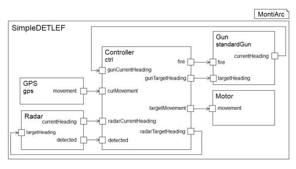
Simple Deflef with components GPS,
Motor, Controller, Gun and Radar.Depending on the information received from GPS and Radar the Controller component controls the movement via sending commands to Motor and the Gun by determining whether it should shoot and where it should point to. This chapter of the tutorial conveys the very basics of MontiArc. In the first part, you will read about MontiArc and Robocode. After that, you get to implement parts of Simple DETLEF. You will implement the Gun component of Simple DETLEF, add it to the architecture, and finally implement its behaviour. Furthermore, you will define Simple DETLEF's central control unit, which is the Controller.
Task 1.1: Create a Gun Component
component AlarmCheck {
- port
- in SwitchStatus,
- in DoorStatus,
- out OnOffRequest;
- in SwitchStatus,
}
Listing 2.2: Component type AlarmCheck with two incoming and one outgoing port.
In MontiArc, components are the central modelling unit. They encapsulate software parts to be reused in different contexts. They are black boxes, which means their internals are not visible from the outside. Components are either atomic or composed. Atomic components have no subcomponents and have a defined behaviour by, e.g., an automaton or a GPL implementation. Composed components have subcomponents and define their behaviour by the interaction of their connected subcomponents. In MontiArc components are modeled as shown in Listing 2.2. A component definition always starts with the keyword component followed by a type name. Ports are defined by the keyword port followed by the direction of the ports, which is either in or out, the type of the port and optionally the name of the port. If no name is given, MontiArc automatically derives a port name, which is the port's type name starting with a lower case letter.
Simple DETLEF wants to join his first battle. Unfortunately, it has no Gun to prevail against other robots in combat.
It is your task to provide him with a gun component that he can use in his battles in order to destroy other robots. For this, create a file with name Gun.arc in the folder src/main/resources/,
and the package tutorial. The type name of component is Gun. Next you implement the Gun components interface. It has two ingoing ports fire of type boolean and targetHeading of type double, and one outgoing port currentHeading of type double. In addition, it has a component parameter power of type double.
Component parameters are defined in round brackets after the type name of the component.
Task 1.2: Add the Gun as Subcomponent Instance
Component models may be hierarchically composed, therefore MontiArc distinguishes between composed and atomic components. Composed components can contain multiple components, called subcomponents that
can be either atomic or composed again. Atomic components do not have any subcomponents. Subcomponents are connected via directed connectors between exactly one source port to one or more target ports.
Subcomponents are instantiated with the keyword component, followed by the type of the subcomponent instance, and an (optional) instance name. If no instance name is given explicitly, an instance name is generated
(typically the type of the subcomponent, beginning with a lower case letter). Listing 2.1 shows the textual MontiArc model for the composed component LightCtrl. It defines the three subcomponents AlarmCheck, DoorEval and Arbiter (cf. ll. 8ff) and connects their ports (cf ll. 12-18).
Simple DETLEF could use the new gun but it is not integrated in his body, yet. Consequently, he can make no use of his new gun. This has to change! To integrate the newly created component, add the gun component, you
implemented in the previous task, to the Simple DETLEF component. Therefore add the component Gun to the component Simple DETLEF as a. Give it the name standardGun and pass the parameter 5.0 for the firepower of the gun. Parameters are passed by writing the value in round brackets after the type of the subcomponent. Additionally add the subcomponent
Controller with name ctrl to Simple DETLEF.
Task 1.3: Connect the Gun Component
Connectors are used to connect the incoming and outgoing ports of a component type to the incoming and outgoing ports of its subcomponents. All ports of a component and all ports of all subcomponents have to be connected. Each connector has a single source port and one or more target ports. Only ports with the same data type can be connected. There are three types of connectors:
- Connectors connecting an incoming port of a component to an incoming port of one of its subcomponents
- Connectors connecting an outgoing port of a subcomponent to an outgoing port of the component
- Connectors connecting an outgoing port of a subcomponent with an incoming port of the same or another subcomponent
To use the new integrated gun, Simple DETLEF needs to connect the added gun component to his other components.
For the added subcomponents to work they need to be connected to other
subcomponents to communicate. Thus, we need to add connectors between
the added subcomponents and other subcomponents of the enclosing component.
Please, add the missing connectors from and to the subcomponents Gun
and Controller. You can derive all missing connectors from Figure 2.1.
Task 1.4: Implement the Controller behaviour with AJava
Component behaviour describes how messages obtained via incoming ports are processed and which messages are sent via outgoing ports. The behaviour of composed components is defined via the contained sub-architecture. For the definition of the behaviour of atomic components, MontiArc supports three alternatives: behaviour specifications using input/output automata, through embedded Java statements in the component model (AJava), or by extending the generated implementation of the component with a handwritten Java class.
In this task, we will use AJava. With AJava, Java statements can be embedded directly into the component model without creating or writing an external Java class. For embedded Java, simple Java statements (if-then-else, for loop, while loop,...) can be used to describe the behaviour. AJava can be embedded anywhere in the component definition block. An AJava block is marked by the keyword compute followed by curly brackets. Within this block, valuations of incoming ports can be read as if these were attributed to a Java class. Further, valuations of outgoing ports can be set by assigning these values as if they were Java attributes. For example, a value to an outgoing Boolean port outPort can be set within a compute block with outPort = true. Besides, all Java library classes can be imported by writing an import statement above the component declaration, just like you would in Java. Please note that complex data types, as well as employed RTE classes that are not located in the same package as the component model, must be imported.
Unfortunately, Simple DETLEF has no behavioural description he can follow. He does not know how to make use of his components. Consequently, he cannot stand in combat with other robots in his current state. Your task is to help Simple DETLEF to move and to shoot his newly added gun.
When you open the Controller component model in package tutorial you see a TODO in the compute block. The Controller determines the behaviour of Simple DETLEF, which means it controls when the gun of
Simple DETLEF should shoot and where it should point to. Also, it controls the movement of our robot. Your task is to let Simple DETLEF drive in circles, let it shoot when it detects other robots. Both gun
and radar should turn constantly. To achieve this:
- Moving in circles is achieved by increasing the
targetMovement's heading by thecurMovementplus a constant number in range 0-20. To assign a valuexto port
targetMovementin AJava, writetargetMovement = x;.
- You can check the incoming port
detectedof typeDetectedRobotfor whether a robot is detected. When no robot is detected, the value isnull. The value of the outgoing portfiredetermines whether the gun fires or not. - You can change the heading of radar and gun by setting the value of the outgoing ports
radarTargetHeadingandgunTargetHeading. Their current heading is available via the incoming portsradarCurrentHeadingandgunCurrentHeading. - The class
DetectedRobothas the following methods:-
getX()andgetY(): return x and y value of the detected enemy -
getDistance(): returns the distance from DETLEF to the detected enemy -
getHeading(): returns the heading of the enemy in degrees 0 <= getHeading() < 360 -
getVelocity(): returns the velocity of the detected robot
-
Task 1.5: Implement the Gun's behaviour using Handwritten Extension
In this Task we will implement the behaviour of component Gun by providing a handwritten Java class which follows the scheme <ComponentModelName>Impl.java and must be located within the same
package as the component model but in folder src/main/java. Further, the class has to implement the interface IComputable (with its generic type parameters) and implements its methods. Otherwise, the MontiArc
generator will not recognize it. The input and output of the component are encapsulated within a dedicated input and output class with attributes of all incoming and outcoming ports. By implementing the IComputable you have to implement a method getInitialValues() and a method compute(<ComponentModelName>Input). The former one is for setting initial values onto outgoing ports of the component. The latter
one is like the compute block of the previous task and defines the behaviour of the component.
The gun we added to DETLEF in Task 1.2 does not have an internal behaviour, yet. Your task is to define the behaviour of the gun such that it fires in the right direction and at the time Simple DETLEF commands it to shoot.
In package tutorial in folder src/main/java you can find the class GunImpl. Your task is to implement the compute method of the class, i.e., define the Gun component's behaviour. Depending on the value of the incoming port fire the gun should fire. You can fire the gun by calling the function robot.setFire(gunPower). Furthermore, the gun should be turned to the degree of targetHeading. To do so call method
turnGunRight(double heading). At the end, you should return the current gun heading by creating a new GunResult-Object with the current heading and return it.
Task 1.6: Execute MontiArc and Start Your First Battle
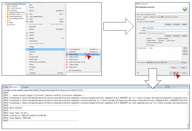
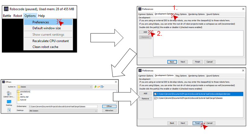
If you have solved both tasks of this chapter, you can test your implementation with Robocode. For this, first, run Apache Maven build as depicted in Figure 2.3. Therefore right-click on your project select run as and click Maven build. Then enter clean install in field Goals. After that, click Run. If you can see Build Success in your console, you can proceed with importing your robot into Robocode. For this, do as shown in Figure 2.4. Select Options and click on Preferences. Then a new window is opened. There click Development Options. In this dialog click on Add. The project explorer should open. Now navigate to the project folder of your robot and enter the target folder in it. Then click Open (or öffnen in German). Now complete the import process by clicking Finish. When you test your robot the next time, it is not necessary to import it again.
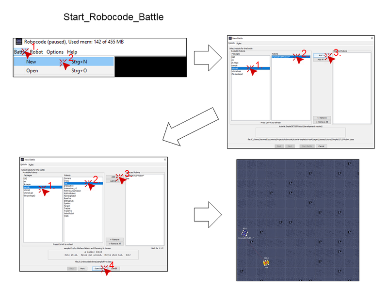
Now we can start a battle and test the created robot. How to start a battle is shown in Figure 2.5. First, select Battle and click New. A new window opens. There you select your robot and arbitrary many competing robots. To start the battle just click Start Battle.
Solution
The solution to the first challenge is available for you.
Challenge 2: Advanced DETLEF
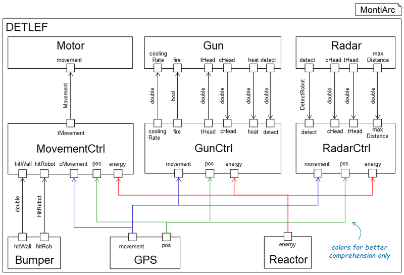
Advanced DETLEF is an improved version of simple DETLEF you know from the previous task. Advanced DETLEF's architecture is shown in Figure 3.1. In comparison to simple DETLEF, advanced DETLEF has distinct controllers for Radar, Gun and movement. In addition, it has a component Bumper that recognizes when DETLEF hits a wall or another robot. With the Reactor it is now possible to take the DETLEF's energy into account when planning actions. In this part of the tutorial, you will learn about embedded I/O automatons in MontiArc and use them to model advanced DETLEF's movement behaviour. Furthermore, you will implement the Drive component, a subcomponent of the MovementController with AJava.
For this challenge, please import the project challenge-02 as described in Section 1.2.
Task 2.1: Implement the DriveModeController with an I/O Automaton
component HelloWorld {
- port
- in String wordIn,
- out String wordOut;
- in String wordIn,
- automaton HelloWorldAutomaton {
- state A;
- initial A;
- state A;
- A -> A [wordIn == "Hello"] / {wordOut = "World!"};
- }
}
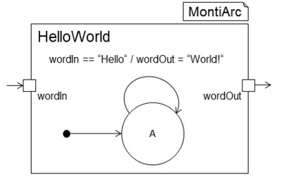
Listing 3.1: Textual version of the component shown in Figure 3.2.
In MontiArc, automatons can describe an atomic component's behaviour. An automaton reads from ingoing ports of the component and, depending on their value it sets values on outgoing ports. An automaton contains a set of states, one initial state and a set of transitions between its states. A transition describes the change of a source state to a target state. It can have a guard and a reaction. The guard is a boolean expression, typically on values of the ingoing ports of a component, that fires the transition when it evaluates to true. The reaction is the consequence of the transition firing. Typically, it sets values on outgoing ports of the component. To indicate that the value of a port is empty you can set or check on this by writing ––. Figure 3.2 depicts a simple automaton describing the behaviour of component HelloWorld. The component has one ingoing and one outgoing port. Whenever the incoming port has the value "Hello", the automaton sets the value "World!" on the outgoing port. In MontiArc, automatons are defined in a textual manner embedded in an atomics component definition. Listing 3.1 shows the textual implementation of the automaton in Figure 3.2. In MontiArc, an automaton definition always starts with the keyword automaton followed by the automaton's name. The automaton itself is defined within curly brackets. At first, all of the automaton's states are defined. The state definition starts with the keyword state followed by the names of all states. One state must be marked as the initial state. Thereafter all transitions of the automaton are defined. A transition can have a guard and a reaction. A guard is a boolean expression over the value of incoming ports and stated in square brackets. The reaction is defined in curly brackets and sets values on any outgoing ports of the component.
Advanced DETLEF has three driving modes Drive, Pong and Crash it can switch between. The states have the following properties:
- Crash:
- -Becomes active when DETLEF crashes into another robot and does not hit a wall. DETLEF stays in this state as long as the crash is not resolved and there is no wall hit. When the crash is solved and DETLEF does not already hit another robot. The automaton switches back to state
Drive. The target movement should be theenemyMovementas long as DETLEF is in state Crash.
- -Becomes active when DETLEF crashes into another robot and does not hit a wall. DETLEF stays in this state as long as the crash is not resolved and there is no wall hit. When the crash is solved and DETLEF does not already hit another robot. The automaton switches back to state
- Drive:
- -Is the initial state of the automaton. DETLEF stays in this mode as long as he does not hit the wall or another robot. The target movement of this state is set to
driveMovement.
- -Is the initial state of the automaton. DETLEF stays in this mode as long as he does not hit the wall or another robot. The target movement of this state is set to
- Pong:
- -This state becomes active when DETLEF hits a wall and no enemy is hit. The target movement is set to
wallMovement.
- -This state becomes active when DETLEF hits a wall and no enemy is hit. The target movement is set to
The target movement of the component can be set via port targetMovement. The target movement of each state is received via the incoming ports wallMovement, enemyMovement and driveMovement. Port crashSolved determines whether the crash DETLEF got involved in is solved. Port hitRobotIn has a value when DETLEF crashes into another
robot and has no value (–) otherwise. The wallHitBearing is the angle in which DETLEF hits a wall. It has a value when DETLEF hits a wall and no value otherwise.
Your task is to implement the above automaton of component DriveModeController in the textual notation. The component is located in folder src/main/resources in package tutorial.movement.
Task 2.2: Implement Driving behaviour of DETLEF
In this task, you will implement the behaviour of DETLEF in the default driving mode. How DETLEF should behave is open to you. You can think of simple solutions such as just driving forward and backward or driving in circles. If you want to implement more advanced driving behaviour, like DETLEF dodging incoming bullets, you can do so.
In the previous tasks, you learned three different ways to model a component's behaviour. You are free to choose any of those to solve this task. For implementing the standard drive behaviour go to folder src/main/resources and open component Drive in package tutorial.movement.
Task 2.3: Deploy and Run Architecture in Robocode
The deployment is similar to Section 2.8. Just make sure that you import the project of this task.
Solution
The solution to the second challenge also is available for you.
Challenge 3: Dynamic Reconfiguration for DETLEF
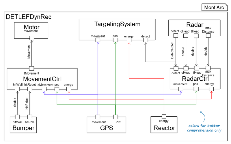
Implementing Dynamic Reconfiguration DETLEF(see Figure 4.1) is the last task of the tutorial. It is the most advanced and mightiest DETLEF of all DETLEF's. In comparison to the robot of the last Task, Dyn. Rec. DETLEF now has a intelligent Movement Control System and Targeting System. Both of them are implemented with the help of dynamic reconfiguration in the following subtask.
For this challenge, please import the project challenge-03 as described in Section 1.2.
Dynamic Reconfiguration
Our approach for modelling dynamic reconfiguration relies on explicit modes, which fully define possible configurations [HKR+16][BHK+17]. A mode is a configuration of a composed component and components can only switch between their pre-defined modes. Components switch between their modes via mode transitions, which are again fixed at design time. Each mode transition consists of a source mode, a target mode, and a guard expression (e.g., over ports of the composed component and its direct subcomponents). Intuitively, when the source mode equals the current mode of a corresponding component instance, and the guard is satisfied, reconfiguration to the target mode takes place. The mode transitions of a component define a state machine over the state space of component modes with the input of data messages observable within the component. MontiArc distinguishes component types and instances. Modes and mode transitions are defined on the component type level of MontiArc. However, at runtime, each component instance reconfigures itself independently based on its current mode and observable messages. Thus there is no synchronization overhead induced by component types. In MontiArc, architectural configurations are defined locally within composed components. For dynamic reconfiguration, we extend the existing single component configuration with multiple modes, where each mode expresses one configuration.
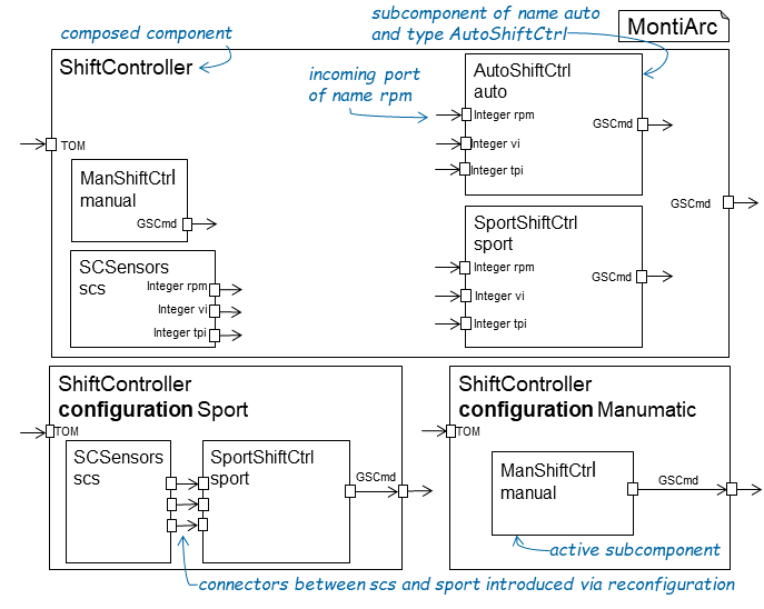
Figure 4.2: Three configurations of the ShiftController component. Top: Initial configuration. Bottom left: Configuration for shifting gears during the transmission operating mode Sport. Bottom right: Configuration for shifting gears during the transmission operating mode Manumatic.
|
Figure 4.2 (top) depicts a C&C model showing the composed component ShiftController. It contains the three subcomponents manual, auto, and sport for the execution of different gear shifting behaviours and the subcomponent scs for providing sensor data comprising the current revolutions per minute (rpm),the vehicle inclination (vi), and the throttle pedal inclination (tpi) encoded as integers. The component ShiftController has an interface of type TOM to receive the currently selected TOM (transmission operating mode) and one interface of type GSCmd to emit commands for shifting gears. Immediately after
engine start up all subcomponents are neither active nor connected (top configuration). Once the currently selected TOM is known to component ShiftController, it changes its configuration accordingly and starts the contributing subcomponents (bottom configurations). While the currently selected TOM is Sport (bottom left configuration), only subcomponents scs and sport are active to emit sensor data and commands for shifting gears, whereas only subcomponent manual is active when the currently selected TOM is Manumatic (bottom right configuration). Making the active components and connectors explicit increases comprehensibility of the architecture. The deactivation of components at runtime has further practical benefits, such as saving computation time and power consumption.
component ShiftController {
- port in TOM tom, out GSCmd cmd;
- component ManShiftCtrl manual;
- component AutoShiftCtrl auto;
- component SCSensors scs;
- component SportShiftCtrl sport;
- modeautomaton {
- mode Idle { } mode Manumatic {/*...*/} mode Auto {/*...*/}
- mode Kickdown {
- use scs;
- use sport;
- use scs;
- mode Kickdown {
- connect scs.rpm -> sport.rpm; connect scs.vi -> sport.vi;
- connect scs.tpi -> sport.tpi; connect sport.cmd -> cmd;
- connect scs.rpm -> sport.rpm; connect scs.vi -> sport.vi;
- }
- initial Idle;
- Idle -> Auto [tom == DRIVE];
- Auto -> Kickdown [scs.tpi > 90 && tom == DRIVE];
- Kickdown -> Auto [scs.tpi < 90 && tom == DRIVE];
- // further transitions
- initial Idle;
- }
}
Listing 4.1: Excerpt of the ShiftController component type definition with five modes (ll. 8-15) and a mode transition automaton.
The example depicted in in MontiArc syntax with support for modes is shown in Subcomponents with instances shared between multiple modes are defined in the body of the composed component and can be activated or deactivated in modes. As an example, the subcomponent scs of type SCSensors is defined in , l. 6 and activated in modes Sport and Kickdown in l. 11. Subcomponents are deactivated by default, e.g., subcomponents manual and auto, ll. 4-5 are deactivated in mode Sport, ll. 10-15. In addition, subcomponents can be instantiated when entering a mode and destroyed when switching to another mode. For example, instances of subcomponent sport of type SportShiftCtrl as defined in l. 12 are unique to modes Sport and Kickdown. Connectors between components are defined for each mode.
Task 3.1: Implement the Movement Control with Dynamic Reconfiguration
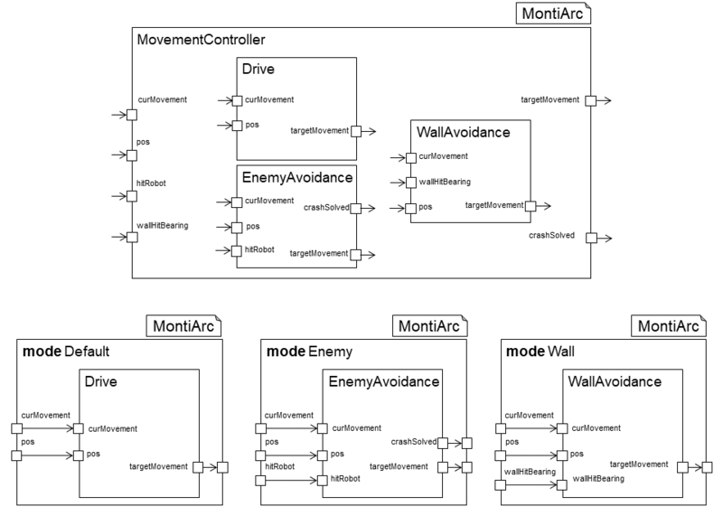
In Section 3.1 you implemented a component DriveModeController. With dynamic reconfiguration, this component is no longer necessary and can be removed. We now model the switching between the different driving components with a mode automaton in component MovementController. After that, he is able to dynamically connect the right driving components. In this task you make component MovementController a dynamic reconfigurable component.
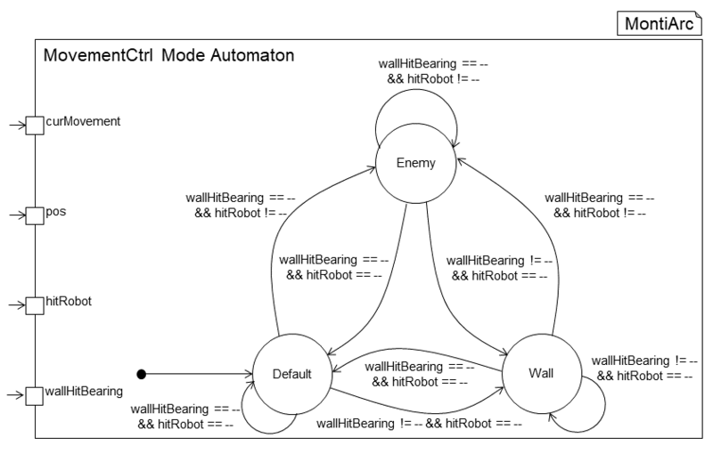
Figure 4.3 depicts component MovementController (Top). It has the three movement controllers you know fromSection 3.1 as subcomponents. The MovementController now has three different driving modes where in each a different movement controller is active and connected with ingoing and outgoing ports of the MovementController. Figure 4.4 shows the input that is necessary for the component to switch modes.
Your task is to implement the modeautomaton of the MovementController according to the graphical description given in Figure 4.3 and Figure 4.4. The component is located in package tutorial/movement in folder src/main/resources.
Task 3.2: Implement the Targeting System using Dynamic Reconfiguration
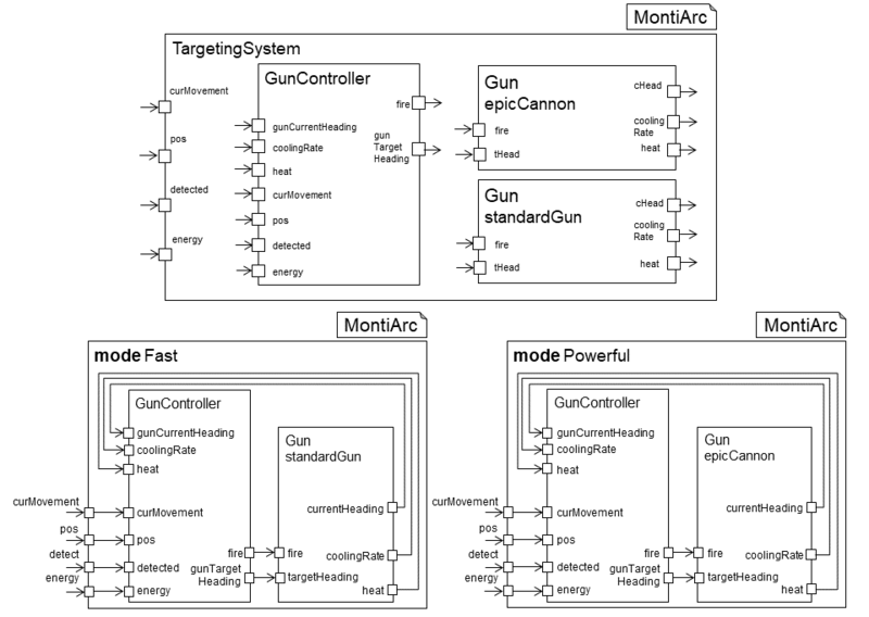
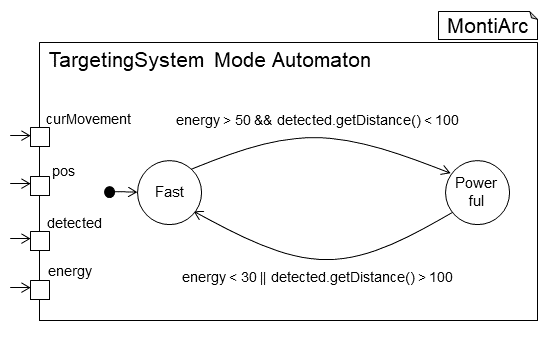
TargetingSystem with a gun controller, a heavy gun called epicCannon and a fast gun called standardGun. (Bottom) The two modes of the system where either the fast or heavy gun is active. In Figure 4.5 the architecture of the new targeting system of Dyn. Rec. DETLEF is shown. It controls the two guns epicCannon and standardGun. Which gun is active is controlled by the mode automaton depicted in Figure 4.6. The initial mode is Fast. In this mode standardGun is active. If DETLEF has enough energy and the the detected robot is in short distance, the targeting system switches to mode Powerful and equips the epicCannon. If energy resources are too short, or the detected robot is too far away to make accurate shots, the system changes back to the fast standardGun.
Your task is, to model the component TargetingSystem and its dynamic reconfiguration automaton. Firstly, create the component model in folder src/main/resources and package tutorial. Then add all relevant ports
and subcomponents of the component (see Figure 4.5). The standardGun should be initialized with a fire power of 0.5 and the epicCannon with 8.0. Then model the different modes and create the mode automaton (see Figure 4.6). It is not necessary to add the TargetingSystem to the general architecture.
When you have finished this task you can test your robot in Robocode again. For the deployment see Section 3.3.
(Optional) Task 3.3: Customize your DETLEF
If you have successfully ran Dyn. Rec. DETLEF in Robocode you are now free to customize DETLEF for the final battle against the other competitors at your workshop.
Show that your DETLEF is the best DETLEF.
Solution
The solution to the third challenge also is available for you.
Battle other Robots
To share your robot, you have to change the name of your robot to a name other than DETLEF, first. You can do this by renaming the top-most component (usually named DETLEF) of the architecture to a name that best suits the skills of your robot. You have to change the name of the model artifact and the name of the component model. Then rerun Maven.
To export your robot just copy the classes folder that resides in the target folder of your task project to a shared storage. From this, others can import your robot by importing the folder to Robocode as shown in Import Task Projects. After that, you can start a new battle and select all competing robots.
Bibliography
[RRW15]: Jan Oliver Ringert, Bernhard Rumpe, and Andreas Wortmann. Architecture and behaviour modelling of Cyber-Physical Systems With MontiArcAutomaton. arXiv preprint arXiv:1509.04505, 2015.
[Wor16] Andreas Wortmann. An Extensible Component & Connector Architecture Description Infrastructure for Multi-Platform modelling, volume 25. Shaker Verlag GmbH, 2016.
[HKR+16]: Robert Heim, Oliver Kautz, Jan Oliver Ringert, Bernhard Rumpe, and Andreas Wortmann. Retrofitting Controlled Dynamic Reconfiguration Into The Architecture Description Language MontiArcAutomaton. In European Conference on Software Architecture, pages 175-182. Springer, 2016.
[BHK+17]: Arvid Butting, Robert Heim, Oliver Kautz, Jan Oliver Ringert, Bernhard Rumpe, and Andreas Wortmann. A Classification of Dynamic Reconfiguration in Component and Connector Architecture Description Languages. In 4th International Workshop on Interplay of Model-Driven and Component-Based Software Engineering (ModComp'17), volume 1, 2017.
- This page was last modified on 13 February 2020, at 13:56.
- This page has been accessed 95,810 times.
